
Audi 200 20 Valve 3B
Timing Belt Change
First, you'll need to acquire some of the important tools needed during this "operation".
Read a service manual. Disclaimer ! Hire a professional!
Be forewarned, doing this incorrectly will damage valves in the interference engine.
You will break valves and damage the motor, costing you expen$ive repairs.
So will neglecting to replace these components every 50K or every 3 years etc.....
This is how we did it. This may not be correct. You're responsible for your own work.

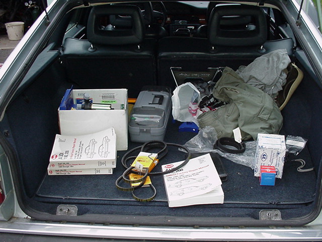
Gather the parts you need:
Timing Belt, Crank Seal, Idler pulley, Water pump, Three Assessory Belts.
Tools you'll need: Hex (Allen) wrenches or sockets 6mm and larger.
Metric 1/2" and 3/8" Drive, deep and shallow 6 point sockets.
Phillips head #2 screw drivers various lengths. Flexible ~10" driver w/socket end.
27, 24mm and smaller metric sockets. Breaker bar or black iron pipe 1 1/2" 4 feet long.
Distilled Water $.50 a gallon, Phosphate free antifreeze. Special Crank Lock tool.
Seal driver and puller tool, Dental pick or seal hook puller. Pliers. (Bentley) Manual
Brillo; scouring pad, sand paper and razor blade. Liquid Penetrant.
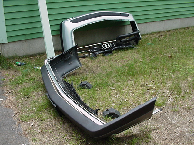
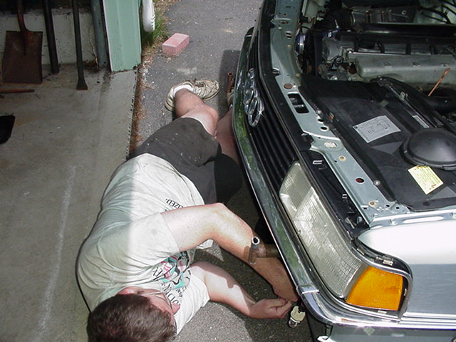
Bumper and Trim off:
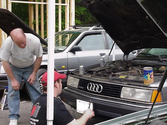
First item is to pop the hood and make sure you have everything: parts, tools.
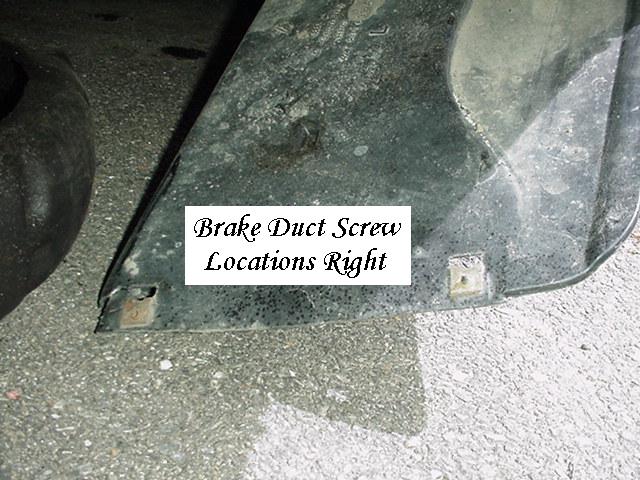
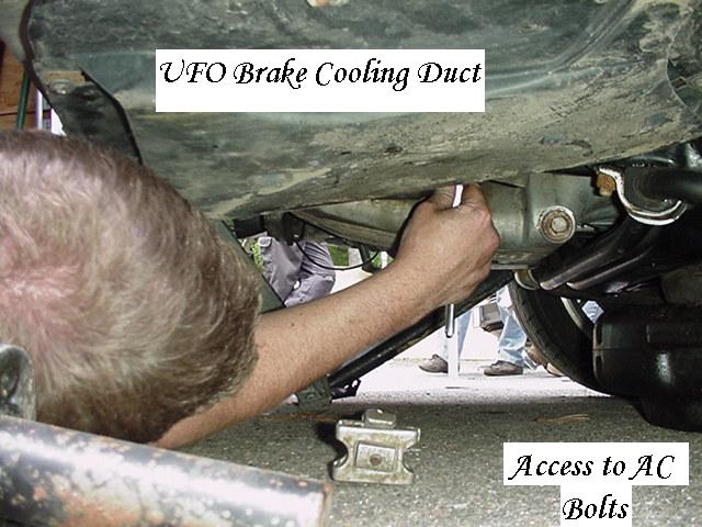
First the brake cooling ducts come down, Phillips head screws 2 each side.
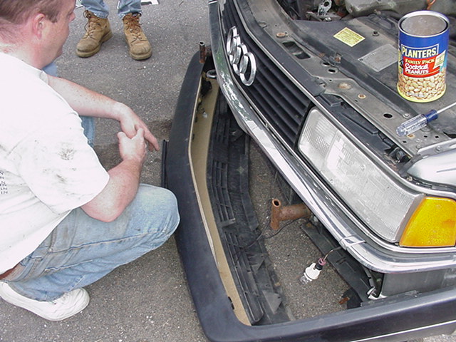
Then the bumper cover can come loose and slide straight out front.

Underneath, inches from the blinkers, are the hex bolts that come out

so you can slide the bumper cover straight out the front of the car.
You'll have to stop a bit out to disconnect the two blinkers. Let bulbs hang.
The chrome trim around and below the headlights is unscrewed first
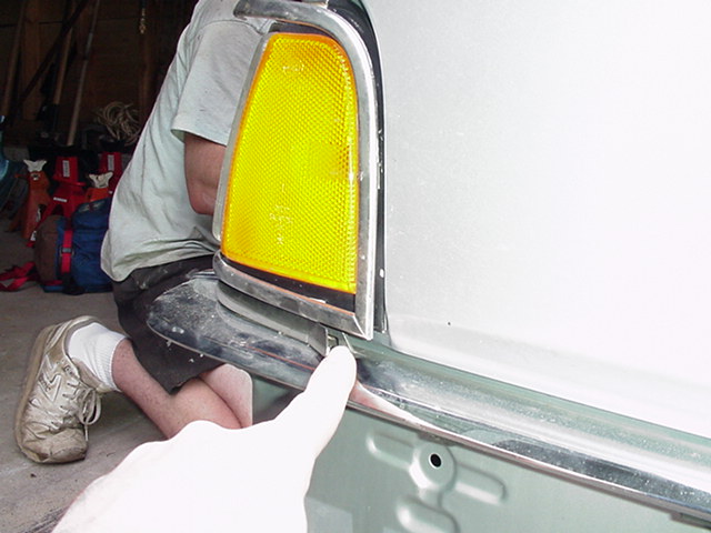

#2 Phillips screws come off. Under the lights is where trim separates.
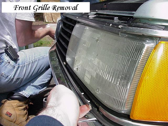
Gently pry the trim off the little "X"'s which hold it on.
Both sides carefully, so next so you can remove the grill.
The corner marker trim chrome can stay.
Intercooler and hoses:
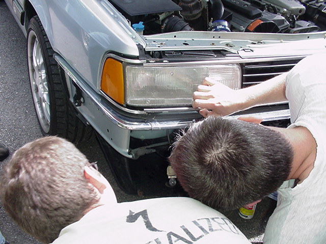
With the grille and bumper gone we can get at the intercooler. (IC)
Now the Intercooler, bumper brackets/supports and crossbar are all exposed.
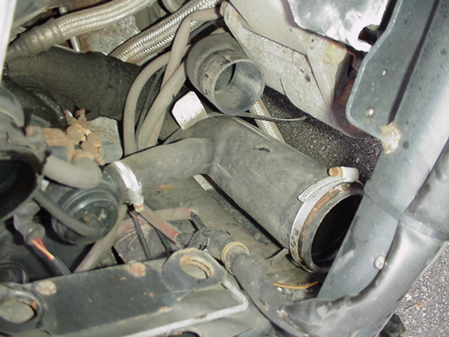
Disconnect the hoses from the turbo area behind IC. The front lower hose
goes through a ridged pipe to IC by the cross member (brace) which we will remove.
Ray and Paul left theirs on and worked around it.
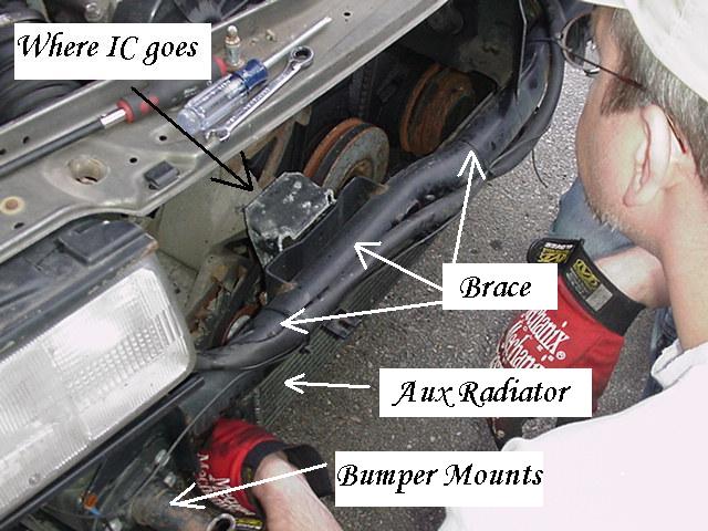
MARK the bumper mounts Left and Right, if they get swapped your bumper
will tilt downwards towards the ground... You can place Aux radiator on the ground.
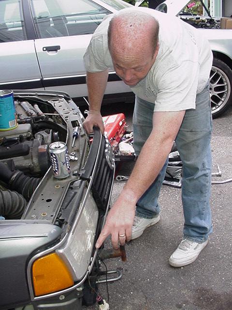
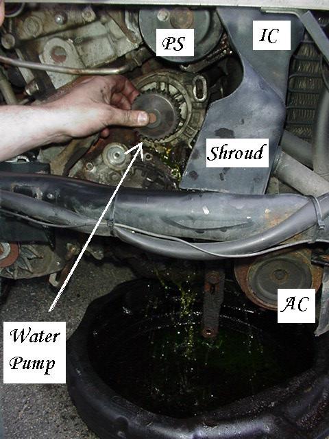
Time to get at the Intercooler so we can see the pulleys and belts behind them.
Now with the Inter Cooler (IC) out we can focus on the assessory belts
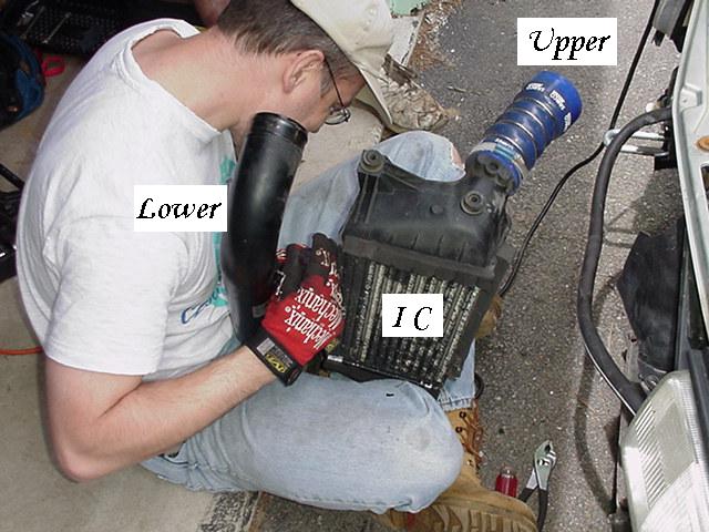
The lower Black crossover pipe is the OEM IC hose which attaches to the lower hose.
Below, Stock OEM lower IC hose, above is the blue Samco Silicone "upgrade".
Inspect for Oil (blow-by) and clean out. Brett says this improves Fuel air mixture ratio.
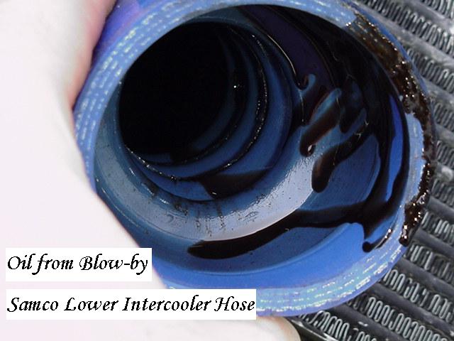
Kinda normal. Not to be alarmed.

Probably a good time to get at the bypass / blowoff valve?
Wastegate frequency Valve?
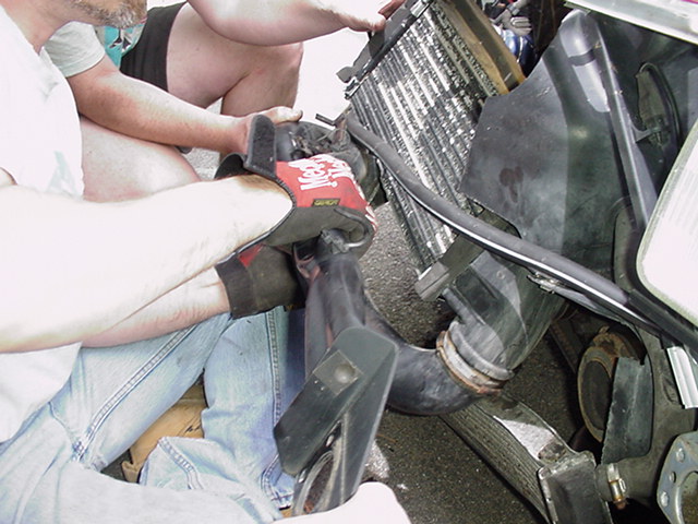
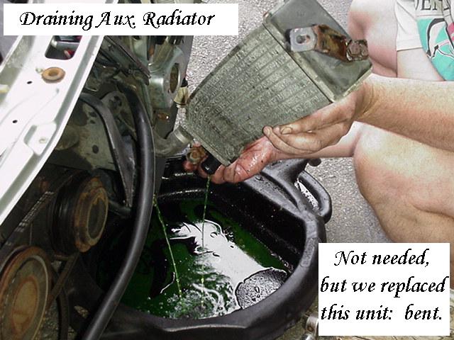
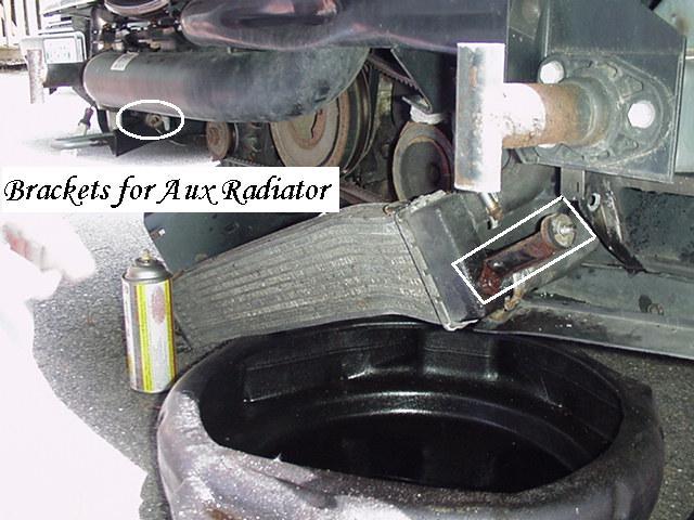
Auxiliary Radiator
During the Timing Belt and Water Pump change, this can be laid aside.
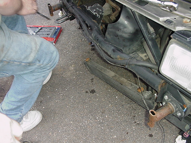
However, this one was replaced because it was damaged.
If you want to flush your coolant, you'll need to do this.
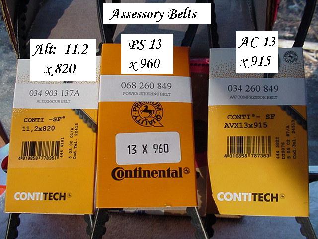
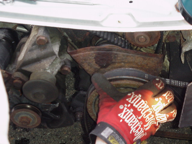
Assessory Belts: Alt, PS and AC.
Time to get at the other belts on the crank pulley.
View of the Assessory Belts, components.
Alternator bracket has three bolts and star adjuster, PS pump has two nuts.
Under the front is several bracket bolts and a tension bar / bracket.

Below is the tension bar out.

AC compressor brackets has two nuts and a star wheel adjuster too.
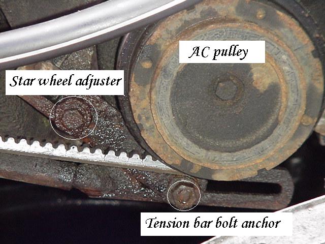
One of the AC mounting / pivots bolt is in the back of the compressor.
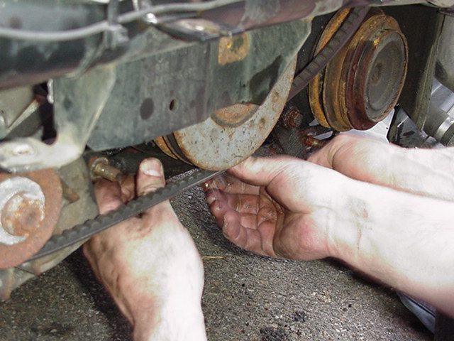
Swing the Alt, PS and AC from tension to remove the assessory belts* (Link).

Here, Peter checks the belts, but we're putting new ones on with the correct profile:

Continental "V" Belts Sizes: (LINK)
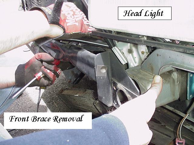
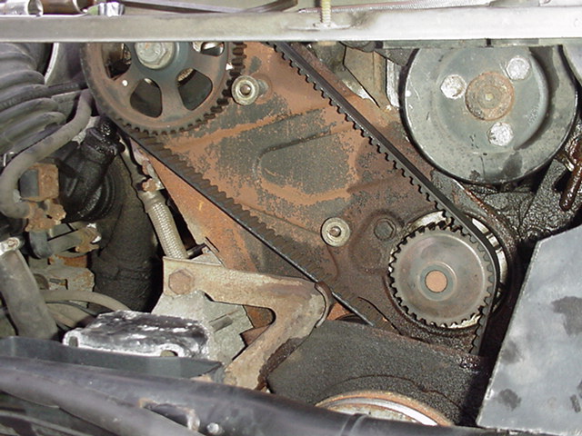
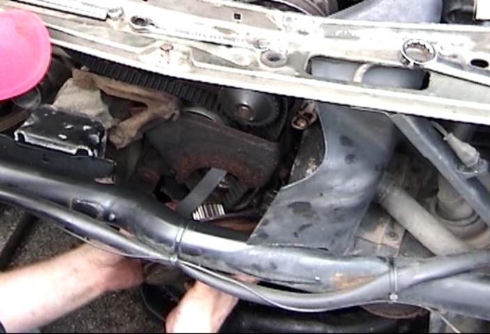
Timing Belt and Covers:
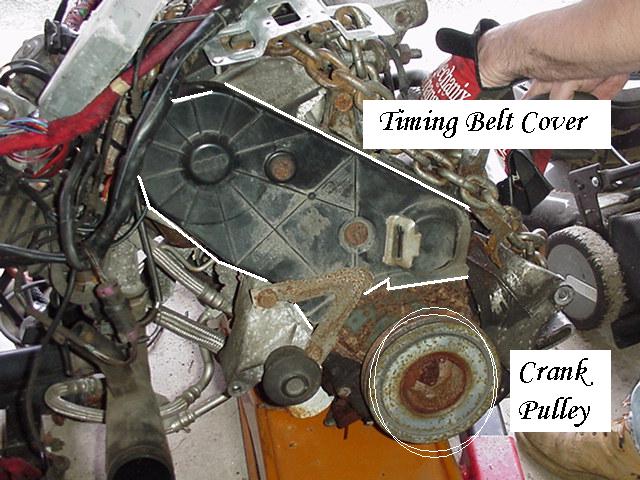
Inside the front frame, now exposed, is the
Black timing belt cover. 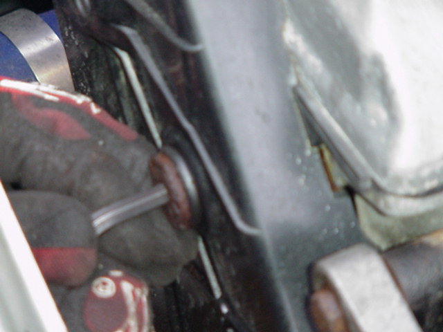
which takes two 6mm hex/Allen sockets or wrenches.
(while you can remove this Upper cover with the IC and grill in place,
WITH SUPER skinny hands, you'll probably strip the 6mm hex heads or puncture the IC)
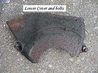
Once that Black timing belt cover is off, then an inner set of covers:

upper rusty metal and a lower (shown) below, by the crank pulley are exposed.
When pulling off the covers, we addressed some clamps,
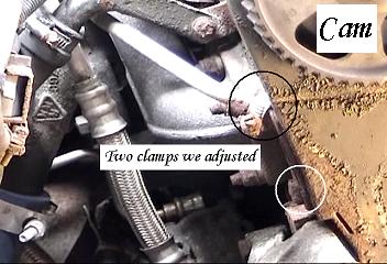
bolts on the Left of the block.
The upper cover shown below CAN be loosen and not removed,
so that you can tilt and slide out (below) the water pump.

Craig slid the water pump under the cover so it is possible.
This is done to keep from pulling the cam timing wheel off. We took it off.
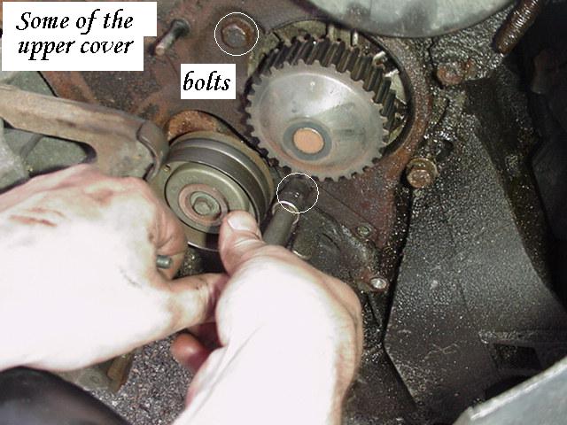
In order to do that we need to pull the Cam Sprocket and the Idler Pulley
If leaving cover on loose, then just the Idler pulley needs to be removed (below)
Idler Pulley:


Here is the Idler Pulley as previously installed. Bolt is SMALL.

Snap it and some is threaded in the engine block. MAJOR problem to remove.
Putting it on is only 12 Ft lbs?
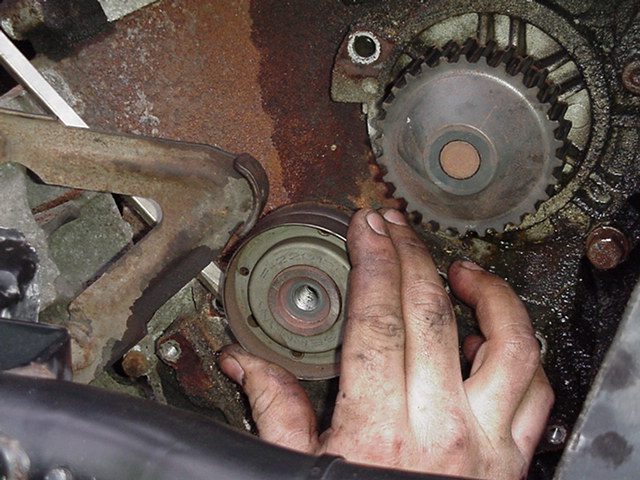
Here, Mike said put a larger bolt in to match the idler's threads.
This would push it off the block in a linear fashion.
Craig threads the bolt in, Ray pulls Idler off wiggling with Pliers on bolt.

Mike, Ray and Craig "team" the Idler pulley off in 22 seconds. (VIDEO)
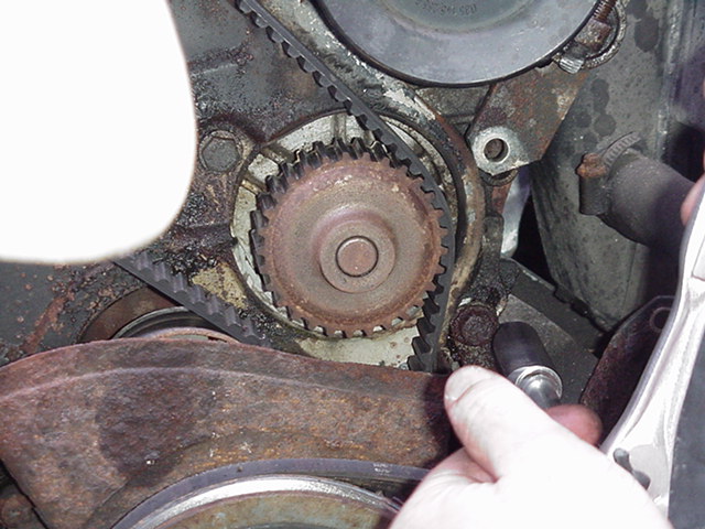
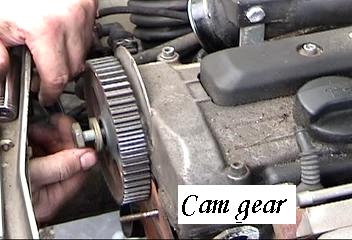
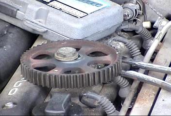
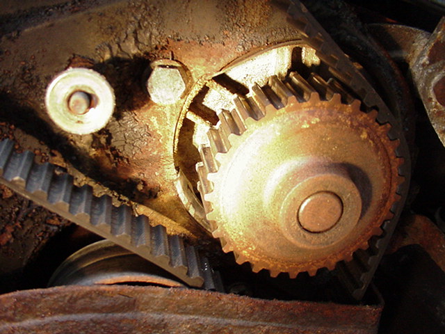
CAM Sprocket - Gear.

Above the wrenches are loosening the upper cover nuts.
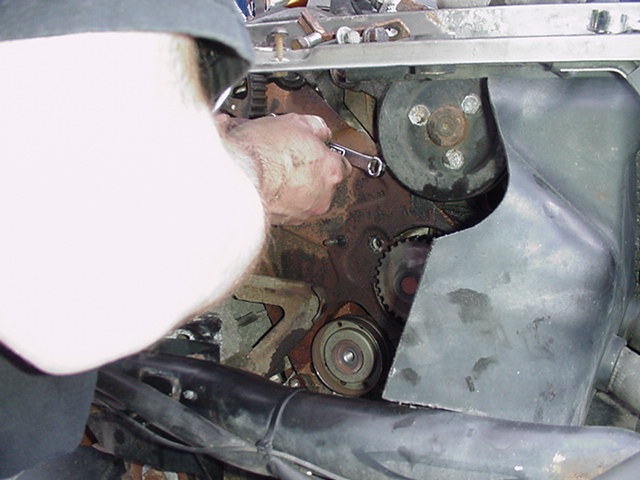
Close up on the Cam Wheel / Sprocket / gear, Timing Marks & window.
I think a screw driver into the casting kept the cam gear
from turning when unbolted.

Once you take off the cam bolt, you cannot turn over (engine) the cam or crank bolt.
You could contact the valves and pistons and bend a valve
or screw up the timing alignment. You WILL reset and double check the
timing alignment BEFORE you re-assemble things.
The Cam shaft is key-wayed, so it will go on as you took it off.
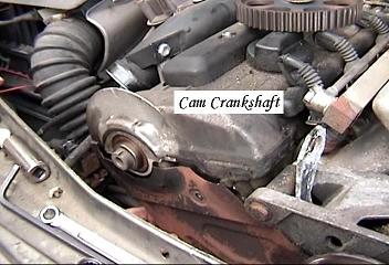
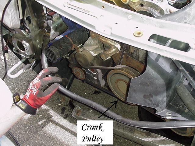
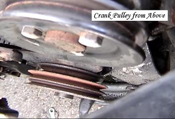
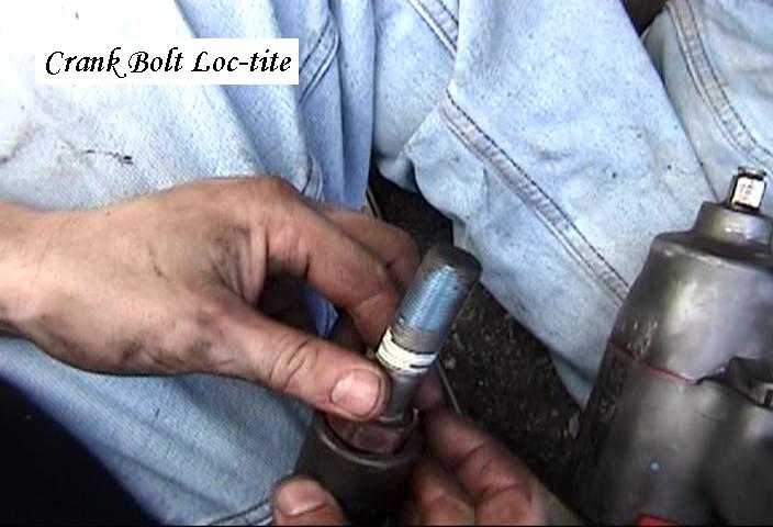
Crank Bolt Removal & Locker Tool:
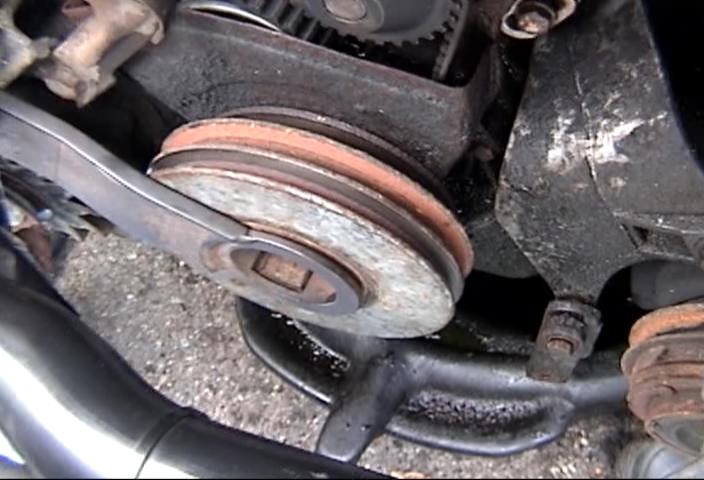
Crank Pulley accepts all three assessory belts on the
outside and is geared to run the timing belt inside.
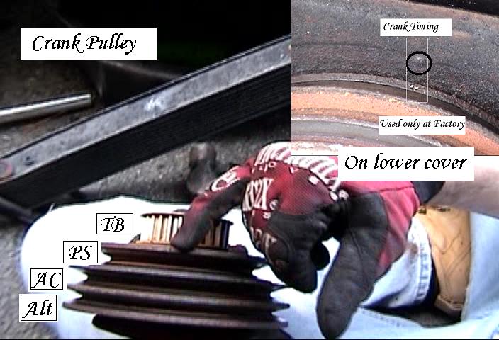
Although it has a "timing" mark on the outside pulley,
it has a rubber isolator / damper within that distorts, so we use realign by
cam timing marks, the flywheel, distributor (if needed) then crank pulley.
Silver one 3256 is for the (S4/6 AAN) motor. Info here:
http://www.sjmautotechnik.com/TROUBLE_SHOOTING/S4timing.htm
The tightening multiplier (Black 6 star-end underneath) NEEDS 3/4" inch drive
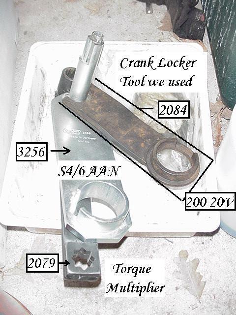
The black one is for the 200 20V, #2084 referenced from:
http://www.sjmautotechnik.com/TROUBLE_SHOOTING/eng.html
Hard to see below but the Crank Pulley has a notch in the center of it. FYI:
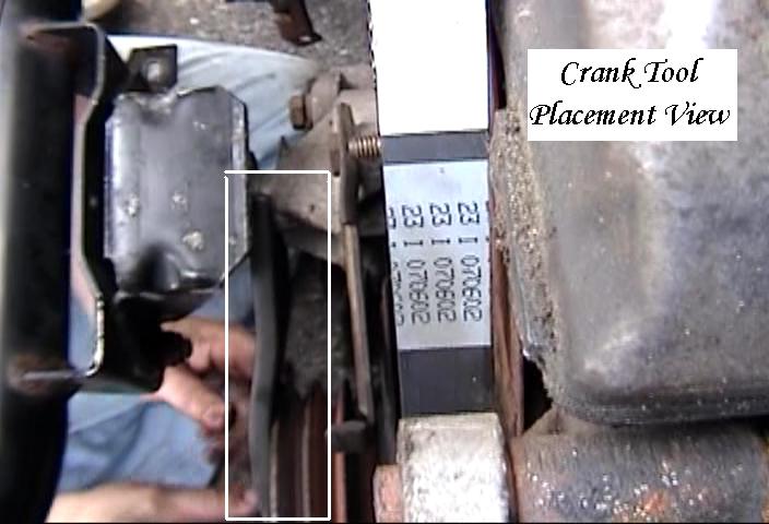
Above view of Crank Lock tool installed, below front view.
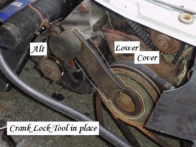
Resting point for the other end of the crank lock tool.

Now you can take out the crank bolt without moving the bottom drivetrain of the motor.
Otherwise, the pistons would be pushed into the valves connected to the cam gear.
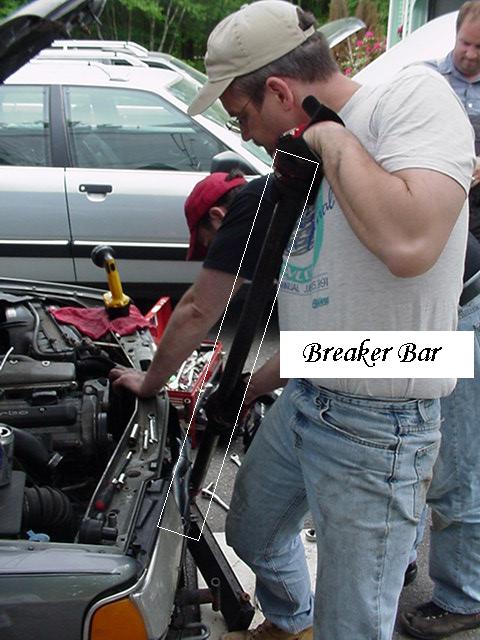
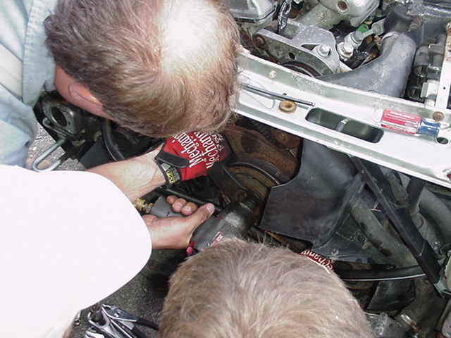
Here Peter puts a breaker bar (Black Iron pipe) to undo the crank bolt.
Align perfectly or you'll strip or shear the bolt head. 27MM 3/4" or 1/2" drive.
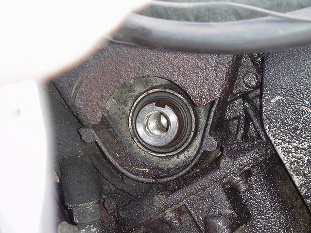
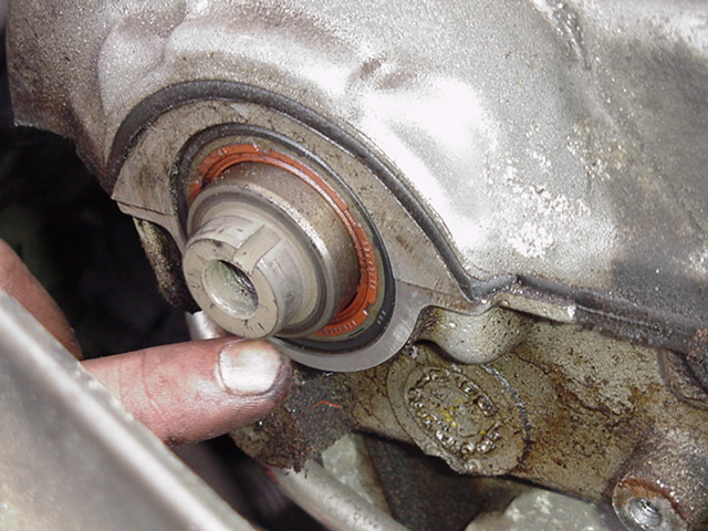
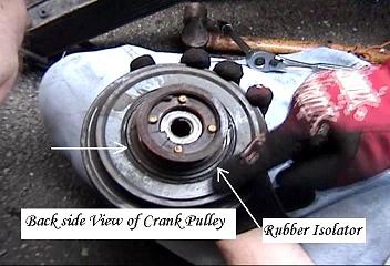
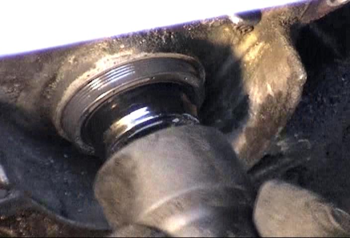
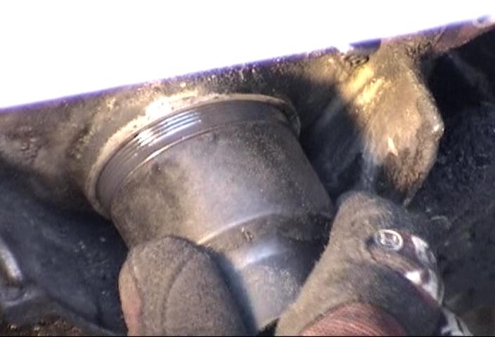
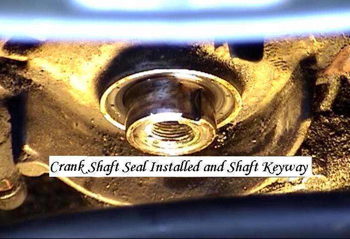
Even with the lower cover still on you can see the keyed
crank shaft and the channel the belt pulley travels in. Pulley removed.

Above is the back of the Crank Pulley
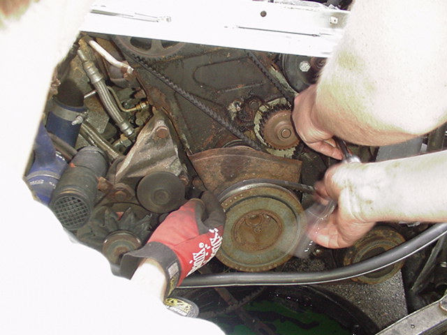
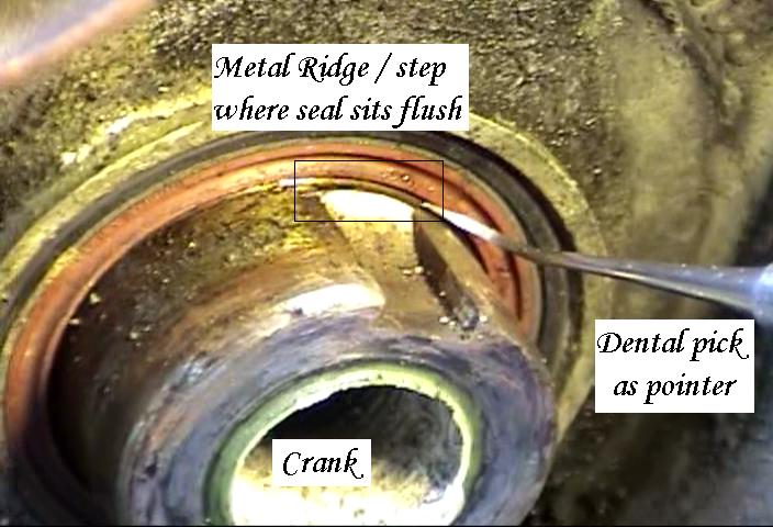
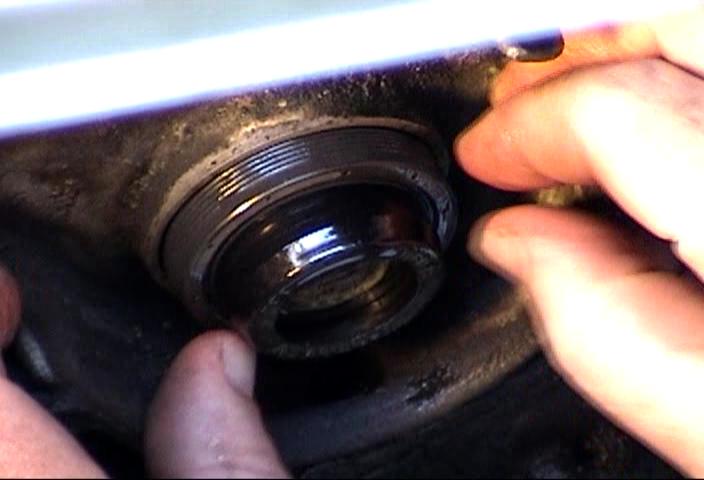
Crank Seal: Removal
Contrary to: "Don't fix it if it ain't broke", we did the crank seal.
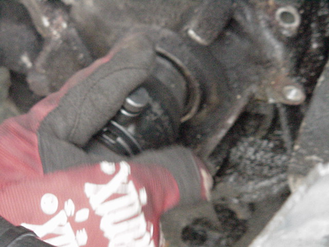
There is a special seal remover tool which we used. WATCH Peter use it.

The end is conical (tapered) with threads that bite into the seal.
Tool center depth is set, then anchored by the pin on the side.
Tool is threaded into the seal by a ratchet, then the pin is removed, the ratchet

is set in reverse and the middle section cranks out the seal tool with the seal.
Dental Pick was used to clean crank surface, seal seat and get seal remnants.
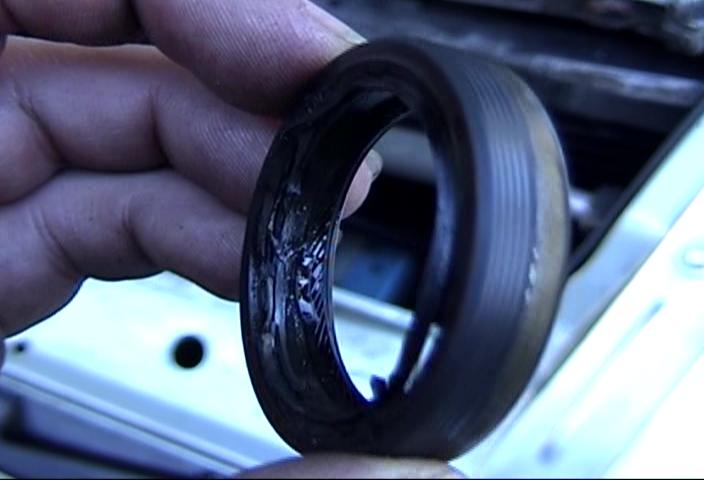
Here is the old crank seal, outer ridges are intact, inside is "chewed" out by tool.
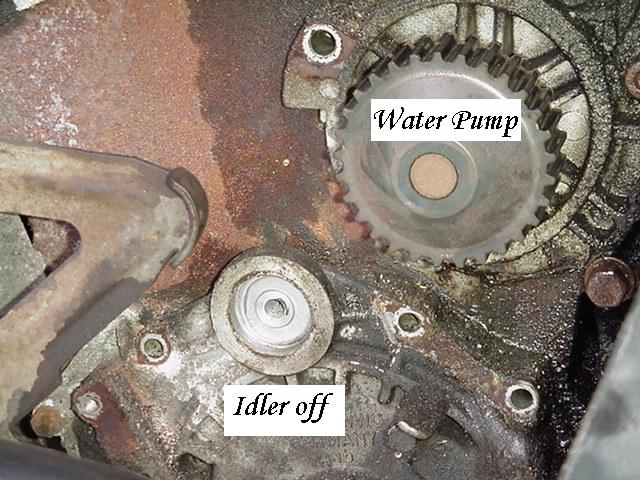
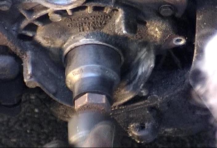
Water Pump
The water pump can be removed at any time, they did it before the crank seal.
Once the bolts around the pump perimeter and Upper cover are gone...
..out goes the Water pump. Now collect and recycle your old antifreeze.

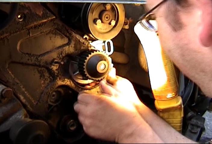
The Water pump is driven by the Timing Belt and its flange is slotted
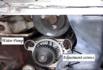
to allow for adjustment of tension when "snugging" up the belt.
Above is how the old pump can be removed, and the new one went in.
With the pump out you can see the thermostat.
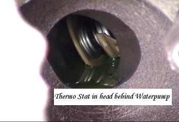

Sometimes the previous installer put sealant around.
A Brillo pad or scour pad can be used too. We razor bladed the seal surface.
Here the pump is in under the upper cover.
Below is the timing belt loose before final adjustment.

Looking good withe the IC shroud there and the Crank Pulley and belt on.
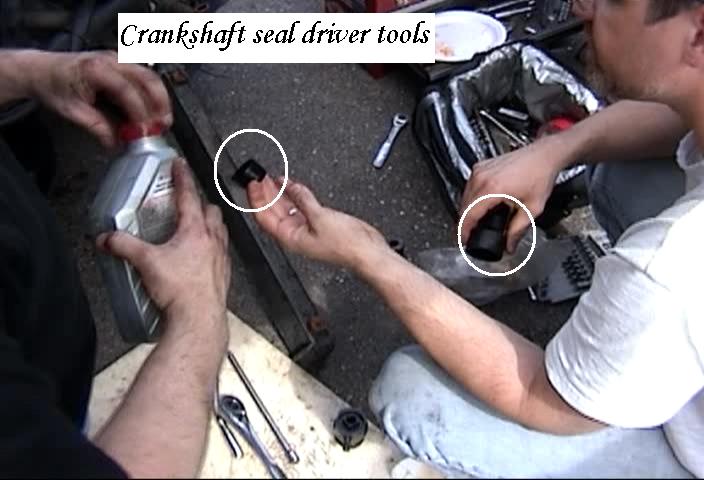
Crank Seal Installation:
This is as far as you need to go with the seal,
the driver tool sets this automatically.
This old seal is not done right, its uneven, seal is out farther at 8 o'clock.
See Ray the "Genius" describe it here in (Video).
After the seal is pulled and the crank bolt threads cleaned,
http://www.zelenda.com/ is a source for Audi tools.
The crank seal depth gauge plastic tool Part Number is: 2080A now 10-203
I referenced some tool numbers from: http://www.sjmautotechnik.com
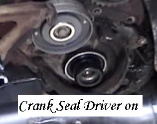
Now its time to drive in a new seal.

Place the seal on the inner plastic depth gauge.
Now with seal flush against the block, the outer driver goes on.
Driver flush on seal.
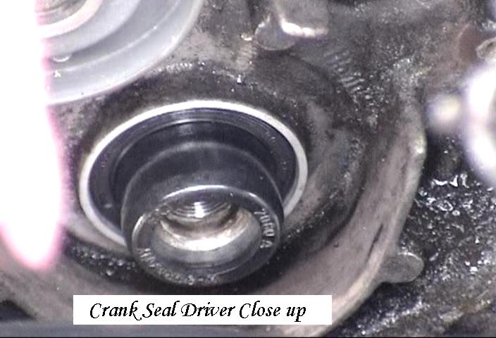
Last look before crank bolt goes in and is
wrenched carefully until it "bottoms out."

There is the actual crank bolt used to drive in the seal.

Hand tightened, using his palm on a ratchet.

Below, pulling the ratchet off the change drive direction to back out bolt.
Remove bolt, seal driver depth tools and you're done.
Crank Pulley Installation
Before you can do the timing alignment you have to put on the Crank Pulley

The Pulley has timing marks which match to the lower cover but they are inaccurate.
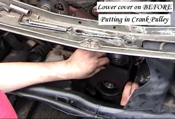
Thread the timing belt down around where the crank pulley goes.

Install the lower cover so the belt is read to accept the Crank pulley.
Here the sequence shows how the Crank pulley teeth align with the belt.
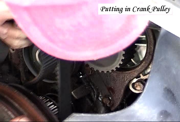
The Crank pulley is keyed, so It will only go on one way.

Once properly aligned with the belt you can thread in the crank bolt by hand.

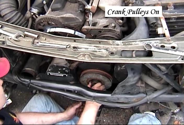
Thread in just a few threads.
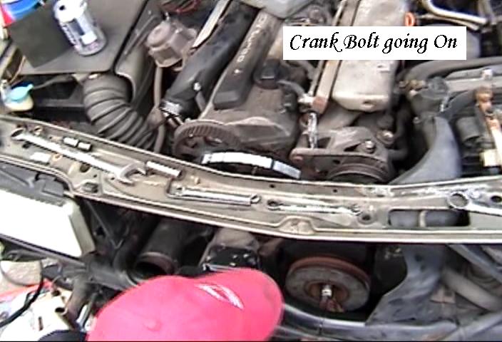
Now its time for the Crank locker tool again.
One.....

Two.....
Alright now, we're ready to set timing marks then fit timing belt.
Setting Timing Marks
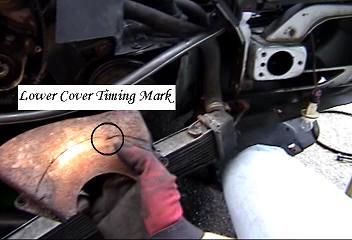
LOWER: The crank pulley mark is inaccurate so we seek the back
of the motor transmission bell housing. (See the VIDEO)
Aligning the timing marks is probably a two person job.
(is the locker tool on?) (Belt on?)

or more.....This cars timing mark was impossible to see clearly.
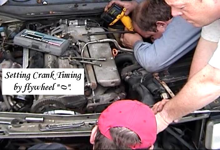
We used a breaker bar to overcome the compression stroke
and make very small movements of the flywheel.

Later we sinched up the bolt by this method to get ~350 Ft lbs.
The crank multiplier tool needs a 3/4" drive to use.
Craig's car had both a "0" and a line (-) on the flywheel.
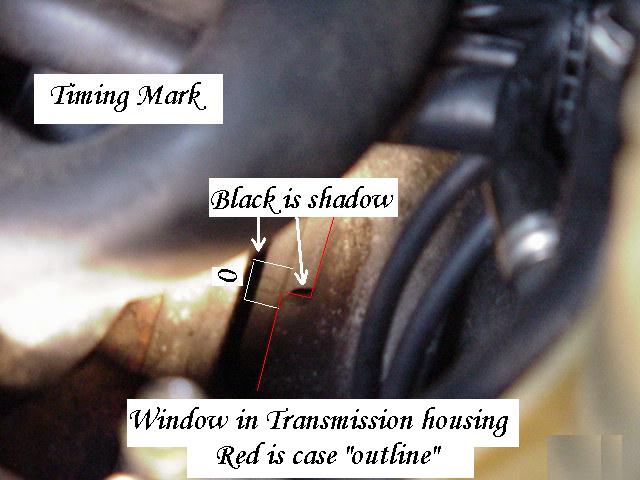
The above photo is KEY to getting this right. It may be VERY hard to see.
One was faded and hidden by light shadows. A flexible light is BEST
UPPER: The cam gear has a dot on the pulley and a "V" Window area.
Ours was SUPER easy to see and align.
Ours was just outside the "V", but after the belt
was put on and the tension adjusted by rotating the engine by hand, it was DEAD on.
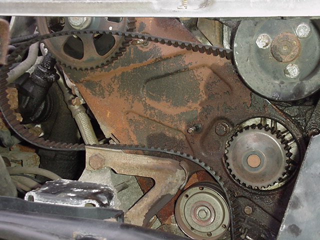
Timing Belt TENSION:
Tension of the timing belt after installation is checked between the Cam Gear
and the water pump on the top loop, and the idler and the Cam gear on the
bottom loop. Both should be equal in tautness and in "twist" tension.
PHOTO
You should be able to twist the belt 90 degrees between idler and cam
and cam and water pump. Adjustments are made at the water pump
then turn over the engine by hand a revolution and check belt tension again.
( PHOTO )
Too tight and it will "whine" and probably leak sooner than later.
Reassembly of the assessory belts, bolts and body parts is:
the "reverse of removal" Muuhahahahahaaaaa.
MAJOR LEAGUE THANK YOU

to: Mike Sylvester who provided the work place and had every broken nut,
bolt and spare parts we needed from parting out several Audis.
Chris Miller's site has additional thoughts and photos
http://members.aol.com/audipage/timing.html
If the site doesn't work, I copied it here.
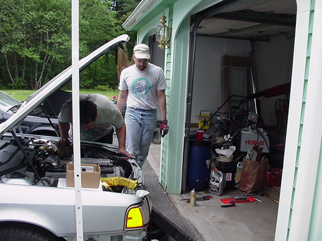
Gallery:
With roughly ~149 built for North America in 1991, 5 in one place is RARE.
Peter and Craig
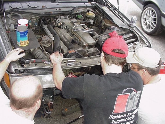
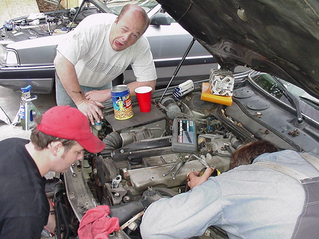
Paul, Ray and Peter
Peter coaching Craig
Paul Hammin' it up.
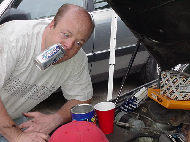
Hands free tin-ny.

Ray looking for a dropped bolt?
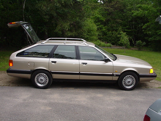
Bambo ~57,000 miles: MINT.
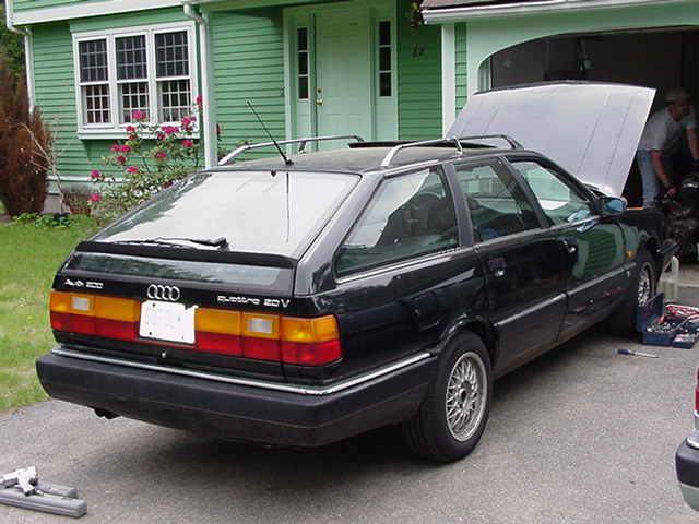
Scott's worn 200 20V. Black is faster.......
Paul and Ray above, Paul and Peter below.

LINKS:
6/14/2004 These will be on-line soon.
22 Megs: Craig and Scott Align the Timing Flywheel Mark See the VIDEO
Crank Seal Ray the "Genius" describe it here in (Video).
14Megs: Mike, Ray and Craig "team" the Idler pulley off in 22 seconds. (VIDEO)
39 Megs: Peter Using the Crank Seal Puller tool. WATCH
38 Megs: Video of Mike and Peter cutting the fuel lines: NOT OSHA approved!
These photos were taken between two cars so the continuity may be slightly off.
The photos are to give you the general idea.
Each photo was selected to as closely as possible, mirror the story line.
![]() by Scott by BOSTON:
by Scott by BOSTON:
![]() to Index
June 2004.
to Index
June 2004.