Audi 200 20V Turbo ECU Upgrade!
Part 2:
READ AHEAD TO FULLY UNDERSTAND THE NEXT SERIES OF STEPS!
Top circuit board will slide right then flip open to reveal lower board
First the male connector needs two flat bladed screwdrivers to depress tabs in the corners.
Then carefully working around the circuit boards all plastic connectors need to be separated.
Yellow plastic usually means brittle old plastic. Go slow & be carefull!
Here's a little guide to slide "right" to separate:
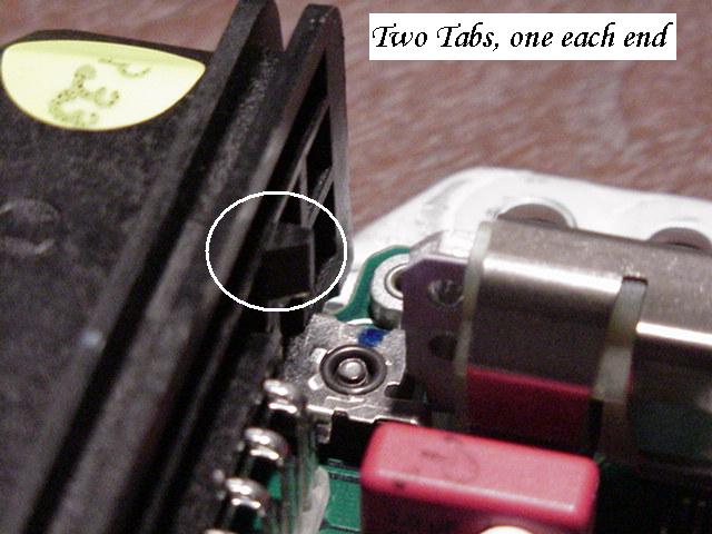
The two screwdrivers above work on these tabs, two at each end of the multi-pin connector
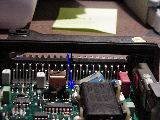
The top circuit board "slides" (right or towards you) out, past the tabs, leaving this
slot AFTER the ridge below is pressed on by a THIRD large flat bladed screw driver.
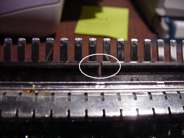
Black plastic ridge under metal contact pins connected to top circuit board.
Notice that ONE of the three rows of pins will slide out leaving TWO rows behind.
Lower pins (two rows) on ECU multi-pin connector and lower circuit board.
CONTINUE:
This end with the connecting wires is like a book binder. Do not split apart!
Opened ECU like a magazine.
Pressure Transducer 2.0 bar or 200kPa. Bosch # 0 273 003 204
Remember the three pins on the bottom edge of the tranducer.
Chip clip: right yellow plastic, hold chip in place. Snap fit.
Very small screw driver pops the clips off the chips. EASY does it.
Opened ECU 1024 x 960 resolution
Click to view Large Photo.
Left, binder, right. Stock ECU with two stickers on two factory ceramic looking chips.
Comparison: TAP modified vs (believed) Stock ECU
Why not work on more than one?
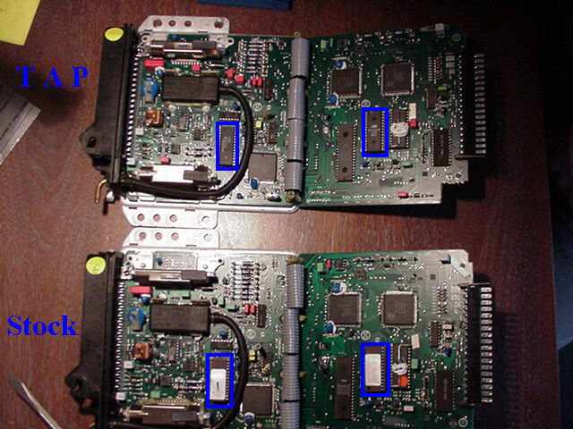
Top is TAP modified, bottom is stock ECU. Only one ceramic chip seems altered/replaced.
On TAP ECU third chip (on lower row) from left is different.
Also noted is the "grade" of chip. Stock is ceramic like: suitable for harsh environment.
TAP upgrade chip appears to be of the (PC) Personal Computer type, less suited for conditions.
Stock above w/ sticker, Tap below with different chip.
Transducer removal:
Here's where the torx # 10 mini bit is needed. Twice.
Right edge is carrier trap to hold circuit board in place.
Above with screws and clips removed we open the aluminum "back" so we can get at back of the circuit board.
Side profile of the metal "back" separated from the circuit board.
Transducer connector contacts: three pins shown by screw driver blade.
Top view of three pins to be removed from circuit board.
Solder wick? Well it "wicks" away the heated solder,
or "makes a more attractive place for the solder to go." - Peter.
One pin loose, only two to go........
Unclipping the transducer from the circuit board.
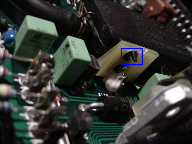
White silicone anchors Transducer and cradle to circuit board. Blue box shows tabs in holder.
Hey its FREE! and off to either be recalibrated or replaced.
DISCLAIMER: This is a guide: not a proven, accredited process approved by Audi or VAG.
Your ECU is about $800 - $2000 U$D. Proceed with extreme caution.
We used two primary references to undo the ECU.
http://www.sjmautotechnik.com/ecurem.html
there is another one too:
http://www.intendedacceleration.com/html/_ecu_removal.html
and some German page referencing Porsche 944 Turbo Bosch ECU's
I made this step by step to help understand each step of the way.
Peter is an engineer, I am not (ME minor though), he is confident with solder, I am not.
You proceed at your own risk, at your own expense.
Here are three tuners of our older year specific, 200 20v 3B motors:
http://www.sjmautotechnik.com/
http://www.intendedacceleration.com
Both have many happy customers. We chose to try Mihnea Cotet in Europe for this ECU mod.
HTH: Hope this helps!